Using the graphical user interface
SWAT-EM comes with an QT based graphical user interface (GUI). The layout of the main window consists of the
Workspace (1)
Winding information’s (2)
Graphical analysis and report (3)
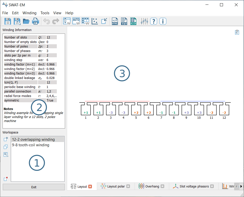
Main-window
Workspace
A SWAT-EM project, that can be saved as *.wdg file, can contain several different windings systems. So, one can define and compare these windings in the same window. The workspace contains all windings of the project. By clicking on a name all plots and reports are changed to the selected winding. The buttons on the left of (1) in figure (Main-window) modifies the windings in the workspace
- New winding
Opens a dialog with all existing winding generator (see section winding generators). One can choose any of these generators to create a winding layout. The generators are also available in the upper toolbar and the main menu.
- Clone
For modifying windings one can clone/duplicate an existing one. So a switch-back to the initial state is possible for comparison.
- Notes
If there a many windings in the project it might be a good idea to add some notes to the different layouts.
- Delete
Deletes the selected winding.
While saving the project to file (File \(\rightarrow\) save) all windings of the workspace are saved. Note: Renaming of windings is possible by double-clicking on it or by pressing F2 on keyboard.
Winding information
The text field (2) in figure (Main-window) shows a summary of actual winding.
- \(Q\)
Number of stator slots
- \(Qes\)
Number of empty slots (no coil sides in it)
- \(2p\)
Number of poles
- \(m\)
Number of phases
- \(q\)
Number of slots per pole per phase \(q=\frac{Q}{2pm}\)
- \(layer\)
Number of winding layers
- \(cs\)
Coil span (in slots)
- \(kw1\)
Fundamental winding factor (for separate for each phase)
- \(\sigma_d\)
Double linked leakage (based on MMF)
- \(lcm(Q,P)\)
Least common multiplier of number of slots an pole pairs. For permanent-magnet machines this is the first harmonic number of the cogging torque
- \(t\)
Periodicity of the base winding \(t = gcd(Q, p)\).
- \(a\)
Number of possible parallel winding circuit. (In most cases \(a\) is equal to \(t\))
- \(r\)
Radial force modes excited by the winding.
- \(symmetric\)
True, if all phases are identically and shifted by a constant angle
- \(Notes\)
User defined description
Plotting
Many results of the analysis are shown as figures (3) of (Main-window). Every plot allows zooming, panning and saving the figure to file.
Winding layout
The winding layout plot shows sketched slots and coil sides. The number and color defines the number of phase the coil side belongs to. The sign (+ or -) defines the winding direction (+ means that the wire goes into the plain and - out of the plain)
Winding layout polar
While the standard layout plot uses cartesian coordinates, the polar plot shows a radial arrangement of the winding. Advantageously one get an impression of the coil connection and if there are overlapping phases.
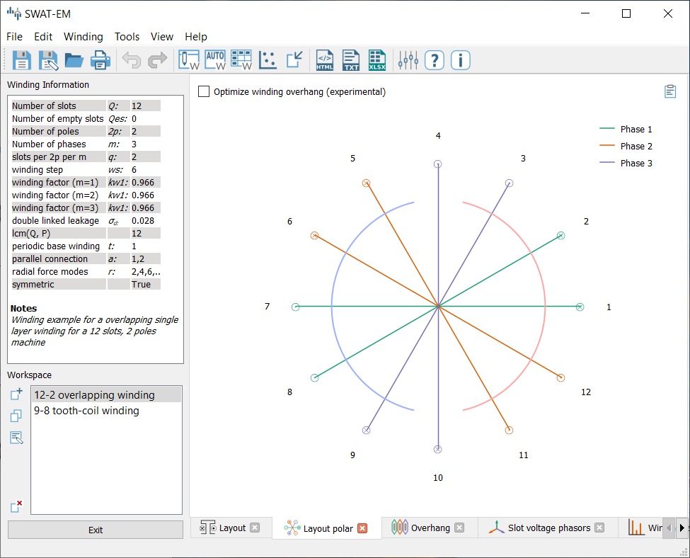
Polar layout plot
Winding Overhang
The winding overhang plot is similar to the polar layout plot. The coil connection are shown in a linear arrangement. Also the size of the end windings can be estimated from this plot
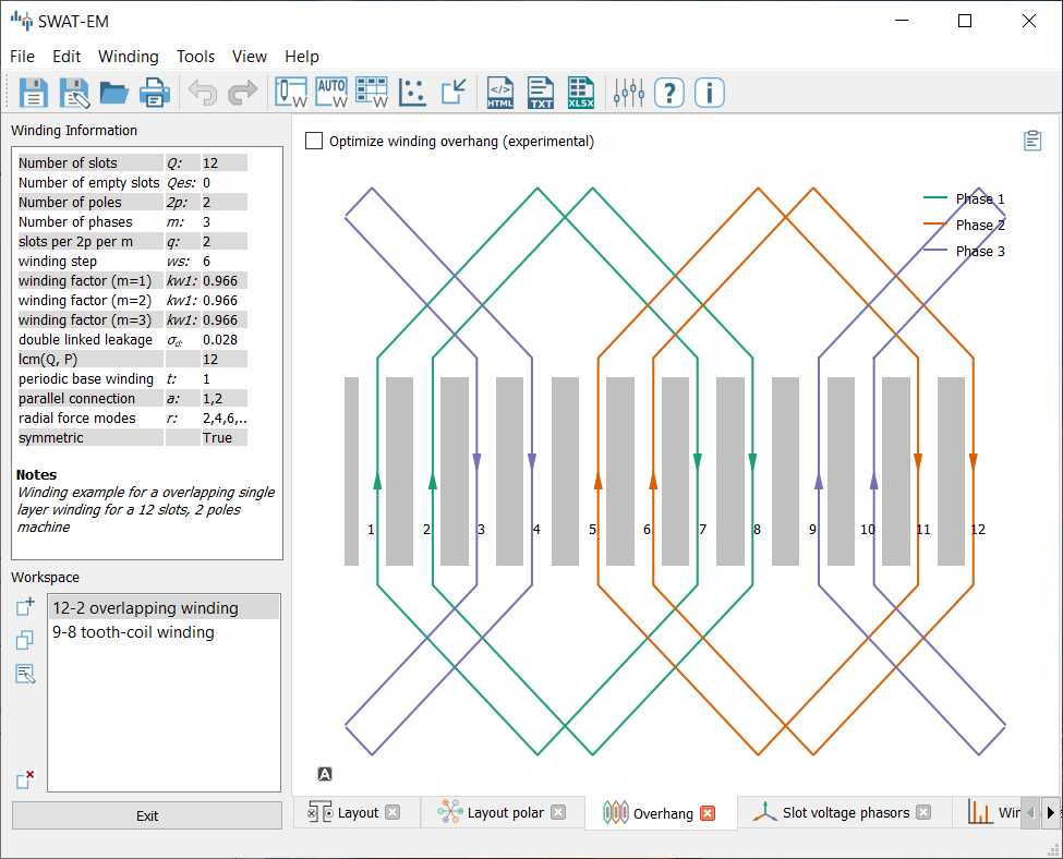
Overhang plot
Slot voltage phasors
The impact of the coils can be represented by the star of slot. The theory behind this is described in [MullerV96] for example. Every coil side \(S_i\) gets a phasor assigned with the angle
The angle of the phasors can also be determined for the harmonics by adding the electrical ordinal number \(\nu_{el}\)
with \(p\) pole pairs and the number of stator slots \(Q\). If the coil side has a negative winding direction \(\pi\) is added to \(alpha_i\) (turning down the phasor). With this the phasers \(E_i\) can be generated in the complex plane
All phasors of a phase are getting grouped a vectorial summed up which is shown as (1) in figure phasors plot. The dotted line represents the vectorial sum. The amplitude and the phase of this is shown in (2).
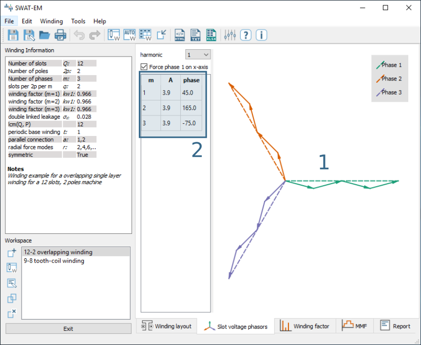
Phasors plot
Options:
- harmonic
The star of slots can be drawn for any harmonic number by using eqn. (1).
- force phase 1 on x-axis
The angle of the sum of phasors depends on the location of the coil sides in the slots. If the whole winding is shifted by some slots the winding is still the same winding. However the phasors are getting a phase shift. To compare different windings in an unified diagram one should set this checkbox.
Winding factor
The winding factor \(k_w\) describes the coupling of the winding with the existing field in the stator (see theory section Winding factor for further informations). Figure Winding factor plot shows the values in (1) as a table and the absolute values as a bar plot in (2). The sign in (1) gives information about the phase sequence of the corresponding harmonic.
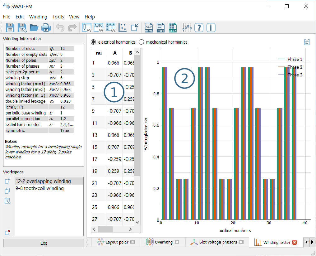
Winding factor plot
Both can be displayed with respect to the mechanical \(\nu\) or the electrical \(\nu_{el}\) ordinal number by the radio buttons on the top of the table.
- Mechanical harmonics
This representation is useful to detect all possible rotor pole numbers, which can be combined with the winding. Especially tooth-coil windings have many harmonics and so there are many pole-pairs possible with a single winding layout.
- Electrical harmonics
If one have chosen a winding and a number of pole-pairs of the rotor it’s a good idea to switch to the electrical ordinal numbers. Here the numbers describes influence of the winding of the waveform of the back-emf for permanent-magnet machines for example. If the winding factor for the harmonics is low, the waveform is more sinusoidal.
Magnetomotive force (MMF)
For evaluation of the winding the so called “Magnetomotive force” or short MMF is a useful tool. It is based on the the ampere-conductor distribution. This is shown for time \(t=t_1\) with respect to the AC current system of \(m\) phases.
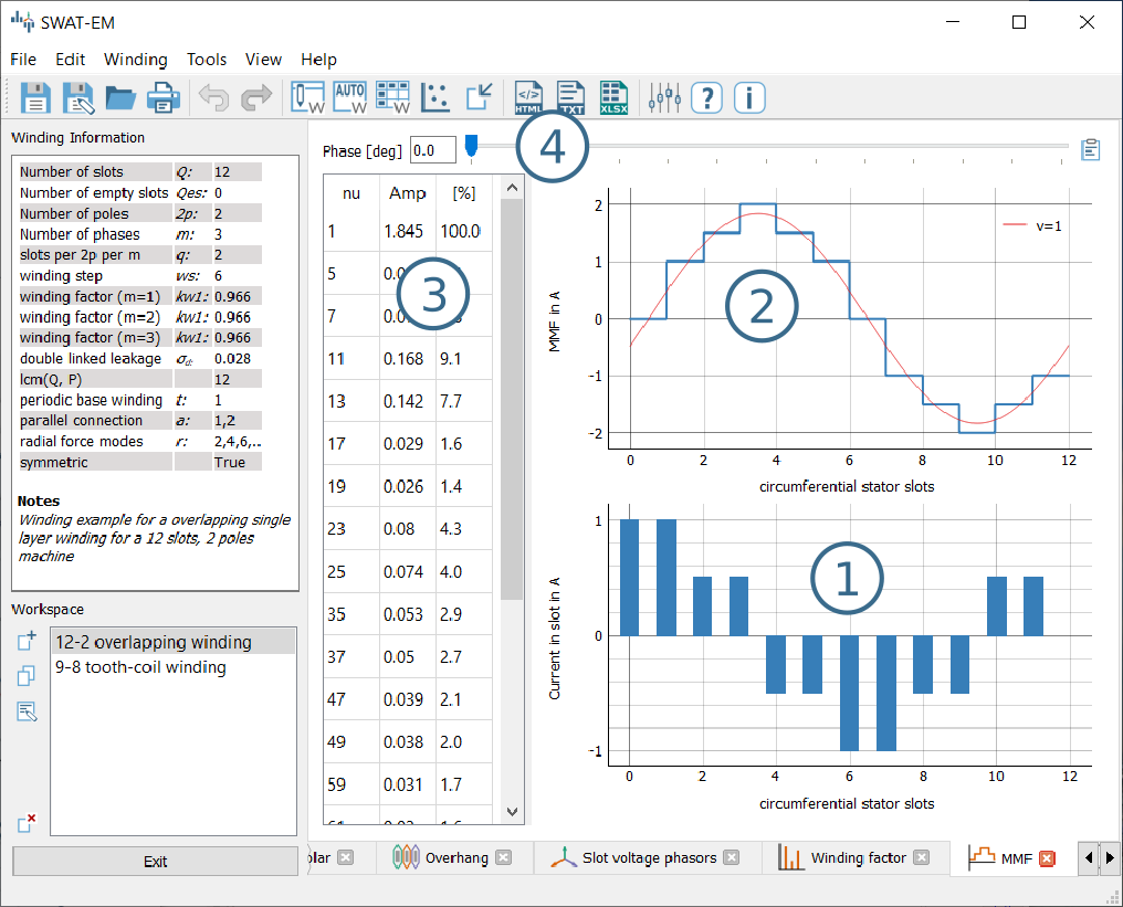
Plot of the ampere-conductor distribution and the Magnetomotive force (MMF)
Figure Plot of the ampere-conductor distribution and the Magnetomotive force (MMF) (1) shows the distribution of ampere-turns. Because this winding example has \(Q = 12\) slots, so there are 12 bars. In reality the distribution has a width per bar which corresponds to the slot opening. However in theory (and in SWAT-EM) the distribution can be interpreted as infinitely thin peaks. The integral of this over the stator circumferential \(\alpha\) leads to the MMF which is shown in (2). The plot also shows the fundamental and some of the harmonics. The number of harmonics which are plotted can be defined relative to the fundamental. Please consider the “Tools” \(\rightarrow\) “Settings” dialog. Table (3) in the window displays the harmonic analyses of the MMF. With the slider (4) one can define the phase angle of the AC current system for the MMF plot. Note that the phase angle has no effect on the harmonic content of the MMF, so the harmonic analyses is independent from it.
Winding Generators
SWAT-EM comes with many different winding generators. Each of them have different features.
Manual layout
The manual layout generator (figure Manual winding generator) is the most basic generator in SWAT-EM. One can define the position and the number of turns for each coil side by hand. With this every winding layout can be sketched and analyzed. The price of it is the comparatively large manual effort.
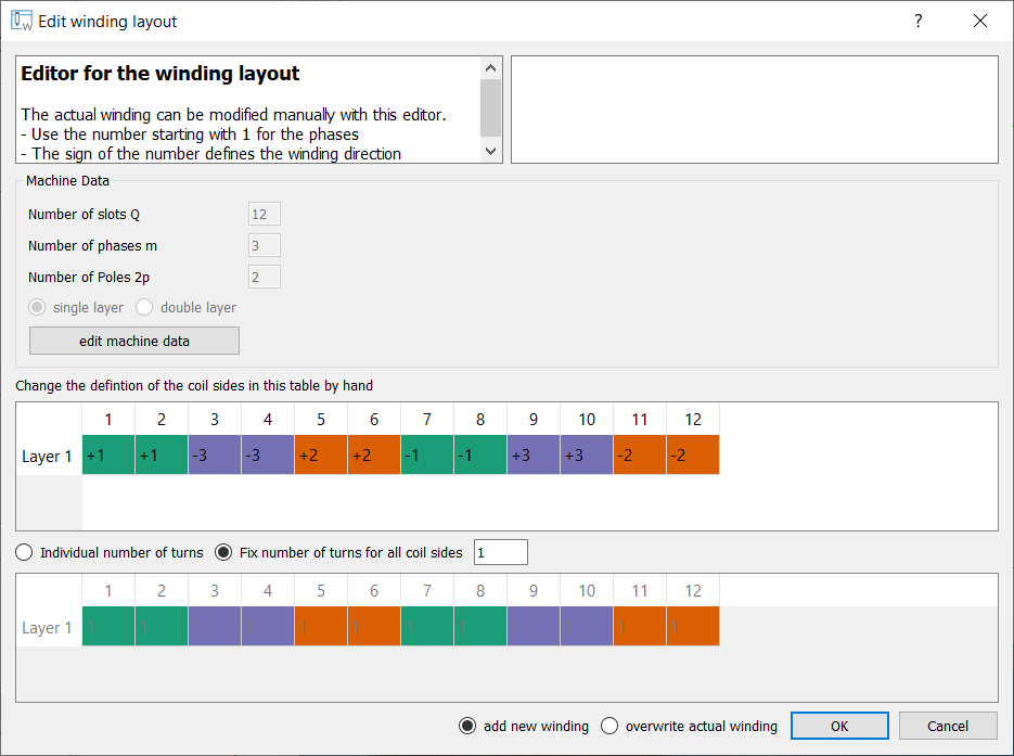
Manual winding generator
- Button “edit machine data”
Use this dialog if you want to change the number of slots \(Q\), phases \(m\), poles \(2p\) or layers.
- definition of the coil sides
Use the table to define the phase for the layers in each slot. The number describes the phase number. The color is added automatically for overview. The sign defines the winding direction (+ into the plane, - out of the plane)
- number of turns
If radio button is set to “fix number of turns for all coil sides” one can type the number of turns in the edit field apart from that. While choosing “individual number of turns” one can define this for each coil side. Use the table below
- info
On the upper right there is an info field. While the user defines the winding there is a live-analysis. If there is an unsymmetrical winding or if the sum of all winding turns is not zero for example, the user get an info.
- overwrite winding
There are two different possible action while exiting an generator dialog with the ok button. If the radio button “add new winding” is selected, the winding is added to the workspace in the main window. If “overwrite” is selected, than the actual selected winding of the workspace gets overwritten. Be relaxed, if you have overwritten your winding accidentally, there is an undo function in the main window.
Automatic layout
With the automatic winding generator it is possible to generate almost every symmetric winding system. This includes
overlapping full pitch winding
overlapping fractional slot winding
tooth coil winding
dead coil windings (with empty slots)
all above as single-layer or double-layer
This generator uses the star of slots to for defining the coil sides in the slots, based on the theory of [BianchiDaiPre06]. For dead coil windings the algorithm of [CDTM+18] is used.
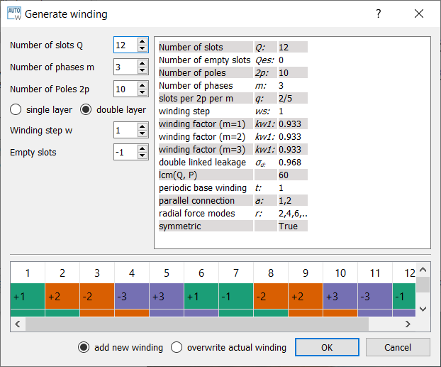
Automatic winding generator
- Machine data
Number of slots \(Q\), phases \(m\) and poles \(2p\)
- layer
Double layer winding means, that in every slot there are two coil sides (from the same or from different phases)
- winding step
Every coil has an “in” and an “out” conductor, which are connected via the winding overhang. The winding step defines the distance between “in” and “out” in slots. If winding-step is 1 a tooth-coil winding will be created. Note: For single layer windings there are some restriction to accommodate all coil sides, so in this case the winding step can’t be influenced.
- overwrite winding
There are two different possible action while exiting an generator dialog with the ok button. If the radio button “add new winding” is selected, the winding in the generator winding is added to the workspace in the main window. If “overwrite” is selected, than the actual selected winding of the workspace getting overwritten. Be relaxed, if you have overwritten your winding accidentally, there is an undo function in the main window.
- layout table
The lower table shows the actual defined winding. Note, that layout can’t changed here by hand. If you want to change, than accept the winding with OK to the workspace in the main window and use the manual generator (section Manual generator). The winding will be transmitted.
Winding table
This generator gives an overview about possible slot/poles combinations. So it’s a generator with a broad but not very deep view on windings. It can be useful in the early state of designing electrical machine, for example to define the appropriate number of slots and poles.
While clicking on a item in the upper table, the winding characteristics is shown on the left side and the winding layout is shown on the bottom table. As with the other generators the selected winding can be transferred to the workspace in the main window.
For some slot/pole combinations there are many winding system possible (different coil span) where this generator shows the winding with the highest fundamental winding factor \(k_{w,1}\). At this time there is no way to modify the windings (changing winding steps for example). For more control you have to use other generators like Manual generator or automatic generator.
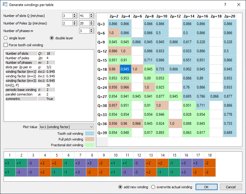
Table of possible windings for different slot/pole combinations
- Number of slots
Defines the range of number the number of slots \(Q\) for the table. For symmetric windings the number of slots must be a integer multiple of the number of phases \(m\).
\[Q = k \cdot m, \text{ with }k = 1, 2, 3...\]For single layer windings (without dead coil windings) the number of slots must be doubled
\[Q = 2 \cdot k \cdot m, \text{ with }k = 1, 2, 3...\]- Number of poles
The number of poles \(2p\). Only even integer values \(\geq2\) are valid.
- Number of phases
The number of phases \(m\) in the machine. Every integer value \(>1\) is valid.
- layers
Defines the number of layers for the table. At this time only single layer and double layer windings are possible.
- Force tooth coil winding
In some cases you may want to realize tooth coil windings, even when the winding factor isn’t very high. In this case the winding step is set to \(w=1\).
- overwrite winding
There are two different possible action while exiting an generator dialog with the OK button. If the radio button “add new winding” is selected, the winding in the generator winding is added to the workspace in the main window. If “overwrite” is selected, than the actual selected winding of the workspace getting overwritten. Be relaxed, if you have overwritten your winding accidentally, there is an undo function in the main window.
- plot value
Defines the number which is shown in the upper table.
- kw1
The fundamental winding factor. A big number (near to 1) means a high-torque.
- q
The number of slots \(Q\) per pole \(2p\) per phase \(m\). It characterized the winding system. \(p = \frac{Q}{2p\cdot m}\)
- t
The number of the periodic sequence of identical “base-” windings.
- a
The number of possible parallel circuits of coil groups in the winding. In most cases it`s the same as \(t\). But for some windings it`s possible to connect coil groups in parallel while changing the start and end of the coils.
- lcm(Q,2p)
Means the least common multiple of the number of slots \(Q\) and number of poles \(2p\). For permanent-magnet machines this is the first ordinal number of the cogging torque. Tends to be true: The higher the ordinal number the lower the amplitude of the cogging torque.
- r1
This shows the ordinal numbers of the radial force mode caused by the winding.
- sigma_d (\(\sigma_d\))
The coefficient of the double linkead leakage flux is a measure of the harmonic content of the MMF in the airgap caused by the winding. As higher the number as higher the harmonics.
Combination Sniffer
The combination sniffer is a powerfull winding generator. With it one can find the best winding for the users requirements. For a given number of slots and poles or - even a range of both - all possible windings (which are implemented in SWAT-EM) are evaluated. The user can select from different target values for the plot:
- \(Q\)
Number of stator slots
- \(2p\)
Number of poles
- \(m\)
Number of phases
- \(q\)
Number of slots per pole per phase \(q=\frac{Q}{2pm}\)
- \(cs\)
Coil span (in slots)
- \(kw1\)
Fundamental winding factor (for separate for each phase)
- \(\sigma_d\)
Double linked leakage (based on MMF)
- \(lcm(Q,P)\)
Least common multiplier of number of slots an pole pairs. For permanent-magnet machines this is the first harmonic number of the cogging torque
- \(t\)
Periodicity of the base winding \(t = gcd(Q, p)\).
- \(a\)
Number of possible parallel winding circuit. (In most cases \(a\) is equal to \(t\))
- \(r\)
Radial force modes excited by the winding.
The scatter plot in Combination Sniffer - Find the best winding is interactively usable. By clicking on a point the corresponding winding ist selected and shown.
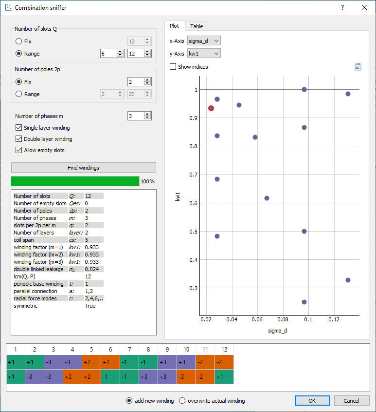
Combination Sniffer - Find the best winding
- Number of slots
The number or a range of numbers of slots \(Q\) to evaluate windings for.
- Number of poles
The number or a range of poles \(2p\). Only even integer values \(\geq2\) are valid.
- Number of phases
The number of phases \(m\) in the machine. Every integer value \(>1\) is valid.
- Single layer winding
If checked single layer winding are allowed
- Double layer winding
If checked double layer winding are allowed
- Allow empty slots
If checked dead coil windings are allows (slots without coil sides)
- overwrite winding
There are two different possible action while exiting an generator dialog with the OK button. If the radio button “add new winding” is selected, the winding in the generator winding is added to the workspace in the main window. If “overwrite” is selected, than the actual selected winding of the workspace getting overwritten. Be relaxed, if you have overwritten your winding accidentally, there is an undo function in the main window.
Winding designs can also selected with the table view (Combination Sniffer - Choosing windings by table).
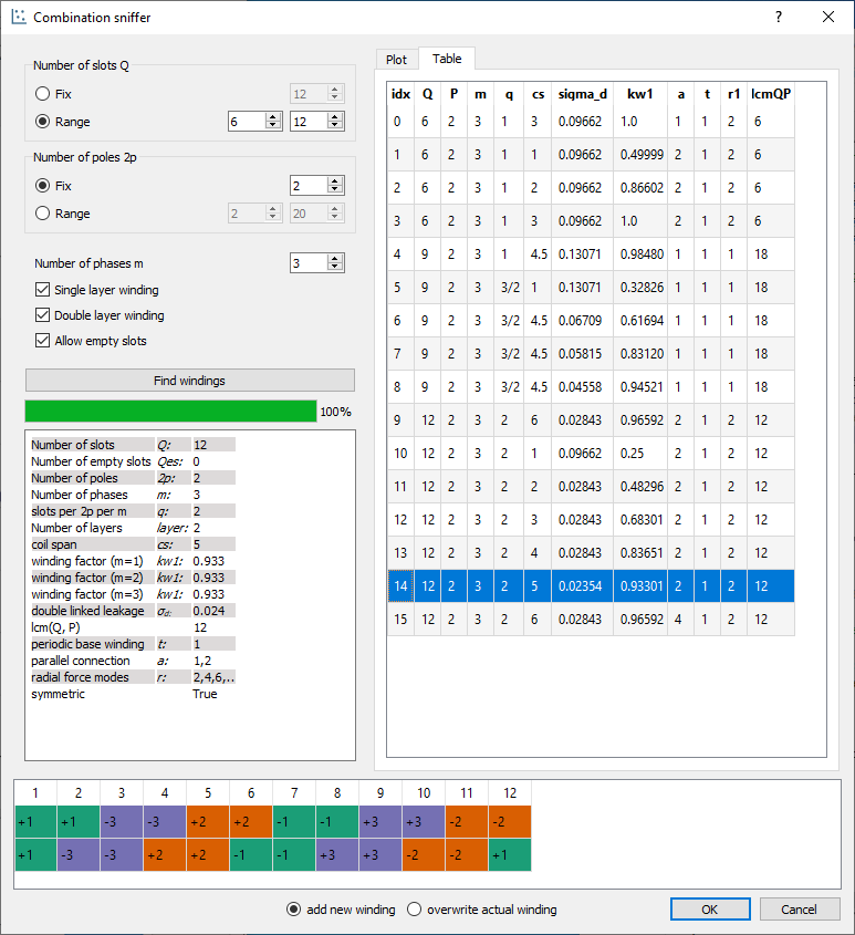
Combination Sniffer - Choosing windings by table
Import winding
As in in Workspace described you can have many winding system in the workspace. In some cases you may want to have a winding in your workspace which is saved as a *.wdg file on the hard disk. This can be done by the import function. A window opens with the file dialog. Navigate to an existing *.wdg file.
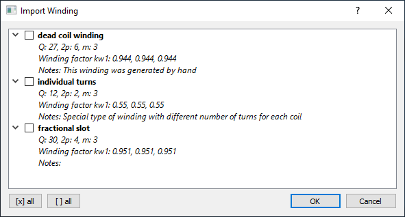
Import winding from file
After that you get a list of all windings systems of the file (figure Import winding from file). Choose all windings you want to import into the workspace.
- CDTM+18
Massimo Caruso, Antonino Di Tommaso, Fabrizio Marignetti, Rosario Miceli, and Giuseppe Galluzzo. A general mathematical formulation for winding layout arrangement of electrical machines. Energies, 11:446, 02 2018. doi:10.3390/en11020446.
- MullerV96
G. Müller and K. Vogt. Berechnung elektrischer Maschinen. VCH, 1996.
- BianchiDaiPre06
N. Bianchi and M. Dai Pre. Use of the star of slots in designing fractional-slot single-layer synchronous motors. IEE Proceedings - Electric Power Applications, 153(3):459–466, May 2006. doi:10.1049/ip-epa:20050284.