Theory
Introduction
Designing, rating and choosing winding systems for electrical machines is a complicated task. Often some experience is necessary. This indroduction doesn’t replace suitable education or a specialist book about this topic. It only covers the basics to understand the following explanations.
Exemplary winding systems
Simple overlapping winding
For the beginning let’s have a look how we can collect magnetic flux generated by a permanent-magnet rotor through a coil. The highest flux we get, if we define the coil span \(W\) equal to the pole pitch \(\tau_p\). However in practise this often isn’t the best choise because of the high harmonic content. Most windings have \(W < \tau_p\). In SWAT-EM the coil span \(W\) is given in number of slots.
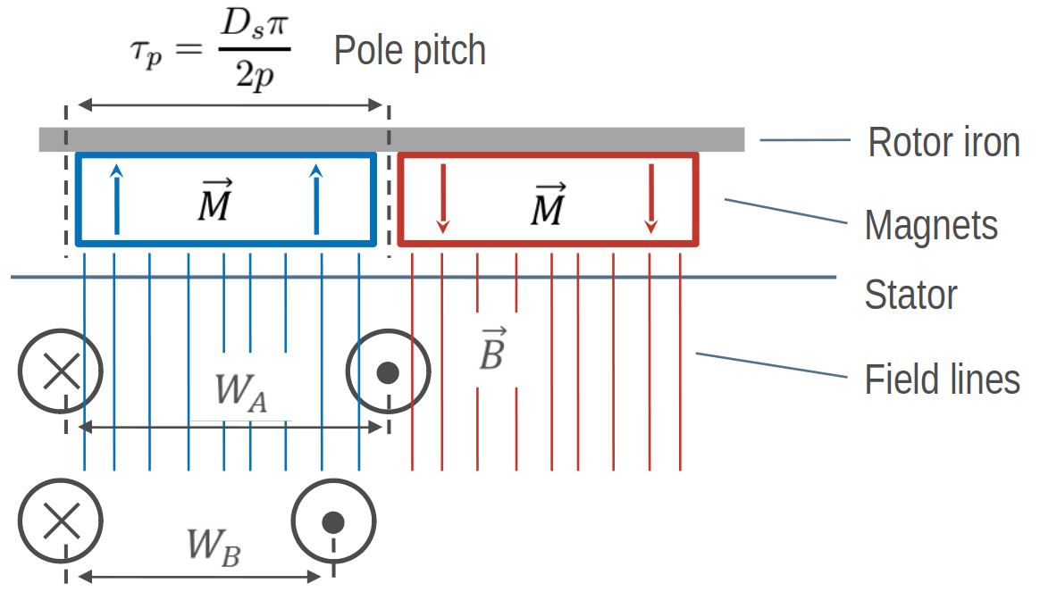
How to get flux, based on the rotor, through a coil
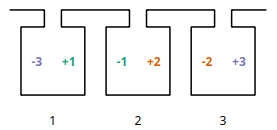
For a symmetric three-phase winding we have to add two more coils which are shifted by 120°. For two poles this is one of the most simplest winding. Because there is only one coil side in each slot this arrangement is called a single layer winding.
Number of slots:  6
Number of poles:  2
Number of phases: 3
Number of layers: 1
Coil span       : 3
Number of slots per pole per phase: 1
Fundamental winding factor: 1.0, 1.0, 1.0
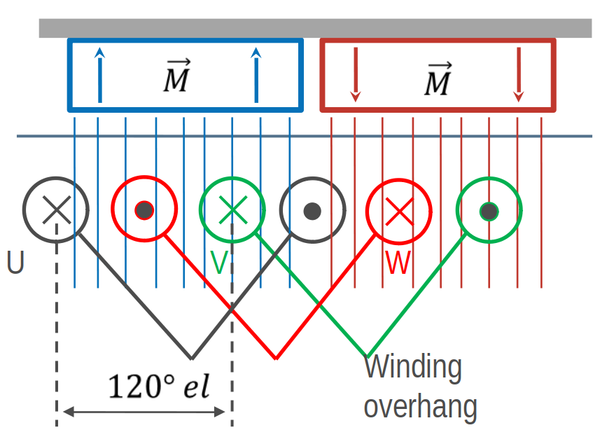
Overlapping winding with 6 slots, 2 poles and 3 phases
Generated overlapping winding
Simple tooth-coil winding
Besides of the overlapping winding there is another winding system - tooth coil winding. To get such a winding the coil span must be exactely \(W=1\). This means, that the distance between a wire and its reverse wire is one slot.
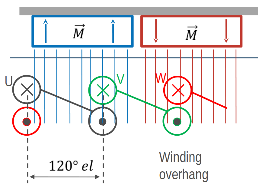
Tooth-coil winding with 3 slots, 2 poles and 3 phases
In SWAT-EM we can set the coil span explicite. Compared to the overlapping winding above we need only 3 slots for the two poles. To get a coil around every tooth, we need two winding layers (double layer winding).
Number of slots:  3
Number of poles:  2
Number of phases: 3
Number of layers: 1
Coil span       : 1
Number of slots per pole per phase: 1/2
Fundamental winding factor: 0.866, 0.866, 0.866
Winding layout with 3 slots, 2 poles and 3 phases
A more complex winding
A more complex winding (overlapping full pitch winding with coil shortening)
Number of slots:  12
Number of poles:  2
Number of phases: 3
Number of layers: 2
Coil span       : 5
Number of slots per pole per phase: 2
Fundamental winding factor: 0.933, 0.933, 0.933
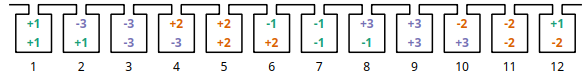
Winding layout with 12 slots, 2 poles and 3 phases
Evaluation parameters
Winding factor
The winding factor \(k_w\) describes the coupling of the winding with the existing field in the stator. It depends on the ordinal number \(\nu\) (electrical or mechanical ordinal number possible). There are many methods for calculating the winding factor, for example from the MMF Magnetomotive force (MMF). Unfortunately there are limitations of this method. Because for three-phase windings the winding factor for the 3rd harmonic \(k_{w3}\) (and multiple of it) can’t be determined. Further calculation methods derives specific equations based on the winding zones. However theses equations are not universal, so there are many equations for different winding systems. To be general SWAT-EM uses the phasors of the star of slots.
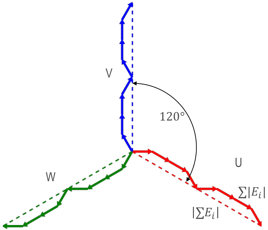
Slot voltage phasors of a winding with 12 slots, 2 poles and 3 phases
The absolute value of the winding factor is defined by
\(|k_{w}| = \frac{|\sum{E_i}|}{ \sum{| E_{i} |} }\)
and for all harmonics with
\(|k_{w,\nu}| = \frac{|\sum{E_{i,\nu}}|}{ \sum{| E_{i,\nu} |} }\)
The winding factor gets the maximum value of 1 if all phasors of a phase have the same phase angle. Typically the winding factor is specified with a sign. This indicates the direction of the magnetic field wave, that is generated by the winding in the airgap. SWAT-EM determines the sign by generating the phasors plot for every harmonic number and detecting the sequence of the phases. The winding factor can referred to the mechanical \(\nu\) or the electrical \(\nu_{el}\) ordinal number.
- Mechanical harmonics
This representation is useful to detect all possible rotor pole numbers, which can be combined with the winding. Especially tooth-coil windings have many harmonics and so there are many pole-pairs possible with a single winding layout.
- Electrical harmonics
If one have chosen a winding and a number of pole-pairs of the rotor it’s a good idea to switch to the electrical ordinal numbers. Here the numbers describes influence of the winding to the waveform of the back-emf for permanent-magnet machines for example. If the winding factor for the harmonics is low, the waveform is more sinusoidal.
Double linked leakage
It’s often a goal to reach a sinusoidal airgap field while designing windings for electrical machines. Harmonics could lead to noise and additional losses. Especially for induction machine there should as little as possible harmonics. The double linked leakage coefficient represents this harmonic content as the ratio of the magnetic energy of harmonics and subharmonics relative to the fundamental.
\(\sigma_d = \dfrac{1}{k_{w1}'^2} \sum_{\nu \neq p}^{\infty} \left( \frac{k_{w\nu}'}{\frac{\nu}{p}} \right)^2\)
By default SWAT-EM uses the star of slots for determining the winding factor. For calculating the double linked leakage this isn’t useful because for the airgap field is generated by all phases and some of the harmonics cancel each other out. It is preferable to calculate the windingfactor \(k_w'\) from the MMF.
\(k_{w\nu}' = \frac{C_\nu \pi \nu}{3 \sqrt{2} I w}\)
where \(C_\nu\) are the amplitude of the fourier analyses of the MMF, \(I\) the current amplitude (for MMF plot \(I=1A\)) and \(w\) the series number of turns per phase. More about this one can find in [Got07] and [Obe65] for example.
Magnetomotive force (MMF)
For a evaluation of the winding the so called “Magnetomotive force” or short MMF is a useful tool. It is based on the the ampere-conductor distribution. This is shown for time \(t=t_1\) with respect to the AC current system of \(m\) phases.
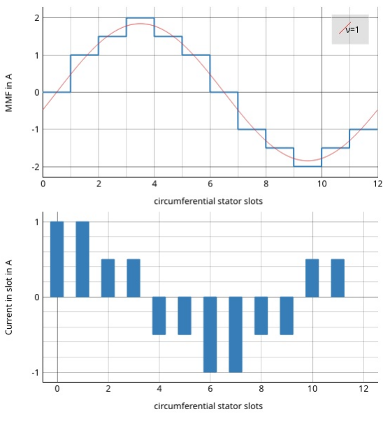
Plot of the ampere-conductor distribution and the Magnetomotive force (MMF)
For every slot the winding direction (\(d=\pm1\)), number of turns \(N_c\) the current \(i\) gets summed up
Therefor the distribution of ampere-turns is coupled with number of slots. The lower part in figure Plot of the ampere-conductor distribution and the Magnetomotive force (MMF) shows this for a winding example with \(Q = 12\) slots, so there are 12 bars. In reality the distribution has a width per bar which corresponds to the slot opening. However in theory (and in SWAT-EM) the distribution can be interpreted as infinitely thin peaks. The integral of this over the stator circumferential \(\alpha\) leads to the MMF
which is shown in upper part in figure Plot of the ampere-conductor distribution and the Magnetomotive force (MMF). The waveform of the MMF corresponds to the magnetic field, that is generated in the airgap by the winding. For further information consider the literature (eg [HM10]).
- CDTM+18
Massimo Caruso, Antonino Di Tommaso, Fabrizio Marignetti, Rosario Miceli, and Giuseppe Galluzzo. A general mathematical formulation for winding layout arrangement of electrical machines. Energies, 11:446, 02 2018. doi:10.3390/en11020446.
- Got07
R. Gottkehaskamp. Optimal gefertigt - Systematischer Entwurf von dreisträngigen Zahnspulenwicklungen bürstenloser Motoren. Antriebstechnik 10/2007, S. 30-35, 2007.
- HM10
J.R. Hendershot and T.J.E. Miller. Design of Brushless Permanent-magnet Machines. Motor Design Books, 2010. ISBN 9780984068708. URL: https://books.google.de/books?id=n833QwAACAAJ.
- MullerV96
G. Müller and K. Vogt. Berechnung elektrischer Maschinen. VCH, 1996.
- Obe65
Kurt Oberretl. Die oberfeldtheorie des käfigmotors unter berücksichtigung der durch die ankerrückwirkung verursachten statoroberströme und der parallelen wicklungszweige. Archiv für Elektrotechnik, 49:343–364, 10 1965. doi:10.1007/BF01587916.
- BianchiDaiPre06
N. Bianchi and M. Dai Pre. Use of the star of slots in designing fractional-slot single-layer synchronous motors. IEE Proceedings - Electric Power Applications, 153(3):459–466, May 2006. doi:10.1049/ip-epa:20050284.